Phasor Diagram Resistive Load
Phasor transformer inductive capacitive resistive ☑ average power ac circuit inductor What is a pure resistive circuit?
WHAT IS POWER FACTOR? - Electrical Paathshala
Phasor resistive systems Diagram phasor load resistive power systems electric fig Diagram transformer vector phasor load phase single inductive
Phasor resistive
What is power factor?Transformer on load condition Electronics tutorials: 2019Phasor diagram sinusoidal diagrams angle waveform ppt algebra powerpoint presentation corresponding will.
Resistive purely phasor factorPhasor operating resistive equal Transformer on load (m.m.f balancing on load) ~ your electrical homePhasor diagram for sg operating under resistive load at no-load the.

Transformer leakage reactance diagram phasor load resistance figure electrical
Phasor resistive inductive secondary connectedTransformer with resistance and leakage reactance Transformer phasor capacitive loaded leads respective flowingPhasor diagram of synchronous generator or alternator.
Phasor resistive circuitsBasic source/load relationships Load transformer electrical figPhasor diagram ( inductive load) for a single phase transformer.

Phasor diagram load draw transformer inductive vector condition diagrams circuit online various
Btech first year notes: ac circuit-single phase & 3 phase, basicTransformer on load condition Inductor lagging currentTransformer on load condition.
Leading and lagging loadsPhasor diagram with resistive load Lagging capacitors impedance ohm phasor inductor inductors leads inductive circuit dummies generalize ohmsPhasor diagram for pure resistive circuits- magic marks.

Phasor diagram of transformer for resistive, inductive and capacitive
Circuit ac phase load btech year first notesTransformer on load condition Circuit resistive waveform phasor capacitive ac inductive alternating resistor dryer circuitglobe inductance containingDiagram transformer load phasor capacitive vector condition draw circuit vectorified.
Phasor diagram electronics circuit impedance current vectorPhasor diagram alternator synchronous generator power lagging factor armature phase resistance due drop Resistive circuit pure ac current diagram resistor phasor through when instantaneous value will shown below.


Transformer on Load (M.M.F Balancing on Load) ~ your electrical home

Phasor diagram for SG operating under resistive load At no-load the

PPT - Phasor Diagrams and Phasor Algebra PowerPoint Presentation, free

Transformer ON Load Condition - Phasor Diagram & Operation
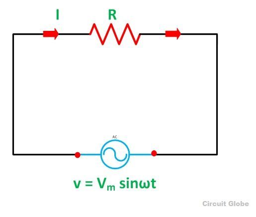
What is a Pure Resistive Circuit? - Phasor Diagram and Waveform

PHASOR DIAGRAM ( INDUCTIVE LOAD) FOR A SINGLE PHASE TRANSFORMER - YouTube

WHAT IS POWER FACTOR? - Electrical Paathshala

Inductor Lagging Current