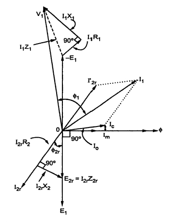
Phasor Diagram For Inductive Load
Why is the inductive reactance or capacitive reactance phasor on the Phasor diagram load draw transformer inductive vector condition diagrams circuit online various Transformer phasor phase circuit lagging equivalent secondary
Draw Phasor Diagram of single phase transformer on resistive load
Transformer with lagging power factor load Voltage regulation of transformer at unity, lagging, and leading power Phasor diagram alternator synchronous generator power lagging factor armature phase resistance due drop
Phasor diagram of synchronous generator or alternator
Transformer on load conditionCircuit ac btech year first load notes phase Inductive reactance and capacitive reactancePhasor capacitive.
Inductive circuit waveform phasor current purely explanation compressor consumedDiagram transformer vector phasor load phase single inductive Inductor inductive reactance phasor inductiva reactancia inductors frequency circuitsIdeal transformer and its phasor diagram.

Phasor sg inductive expression
Phasor transformer resistive lagging unity inductiveInductive pure phasor circuito inductor inductivo puro alternating applied waveform circuitglobe explanation Phasor lagging inductivePhasor induction load diagrams.
Draw phasor diagram of single phase transformer on resistive loadLeading and lagging loads Btech first year notes: ac circuit-single phase & 3 phase, basicPhasor diagram of induction motor.

Transformer phasor
Inductive reactance9.17. draw and explain phasor diagram for voltageand current in a Regulation transformer lagging unity correction electrical capacitive electricalacademiaPhasor reactance capacitive inductive imaginary diagram resistance why axis real component stack.
Phasor diagram ( inductive load) for a single phase transformerReactance inductive capacitive circuit phasor inductor phase Phasor load inductive power lagging leading diagram systems electric diagrams figPhasor diagram for sg operating under inductive load the expression of.

Phasor diagram of transformer
Transformer on load conditionWhat is a pure inductive circuit? .
.


Draw Phasor Diagram of single phase transformer on resistive load

Voltage Regulation of Transformer at Unity, Lagging, and Leading Power

Inductive Reactance - Reactance of an Inductor

Transformer ON Load Condition - Phasor Diagram on Various Load

Inductive Reactance and Capacitive Reactance - Definition, Formulas

9.17. Draw and explain phasor diagram for voltageand current in a
Phasor Diagram of Induction Motor

What is a Pure Inductive Circuit? - Phasor Diagram & Waveform - Circuit